You are hereLighting / Rob's Dimmer Control (layout)
Rob's Dimmer Control (layout)

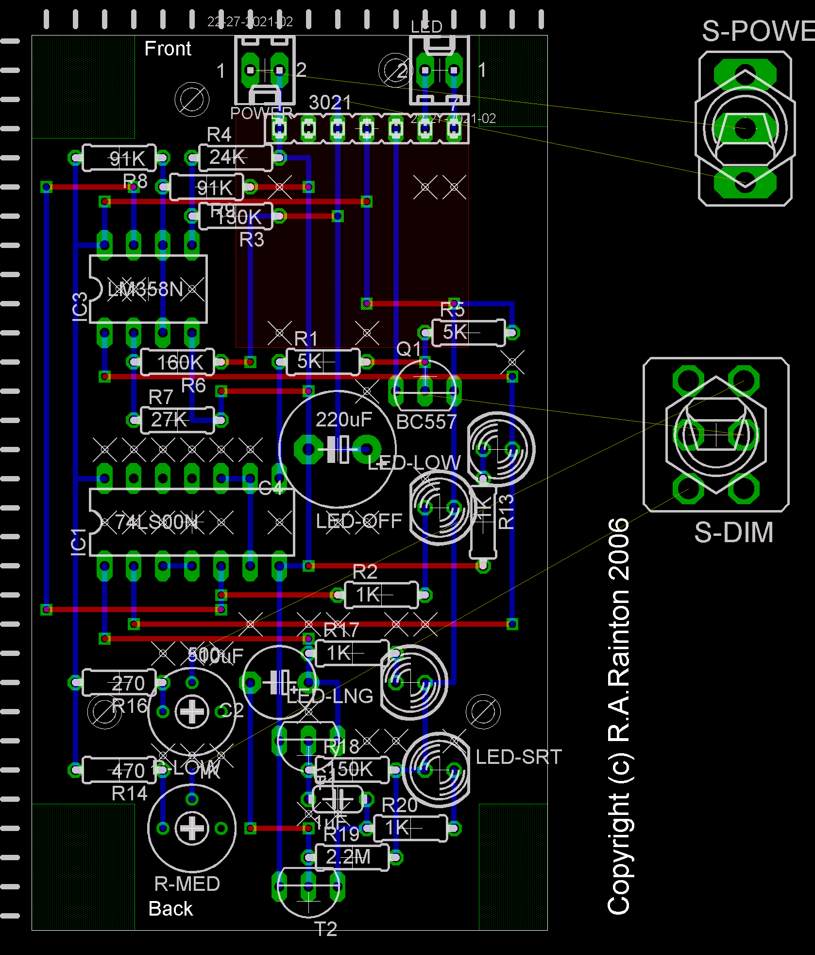
The schematic as laid out on veroboard. Blue = copper on the back, red = wires on the front, white crosses = where to cut tracks on the back.
Note that the power wires will actually be connected just South of the capacitor, but the other unconnected (yellow) wires do indicate pretty well where the dimmer switch will be connected.
See Rob's Homemade LEDs for more about this.


- Login to post comments
- Bookmark & share