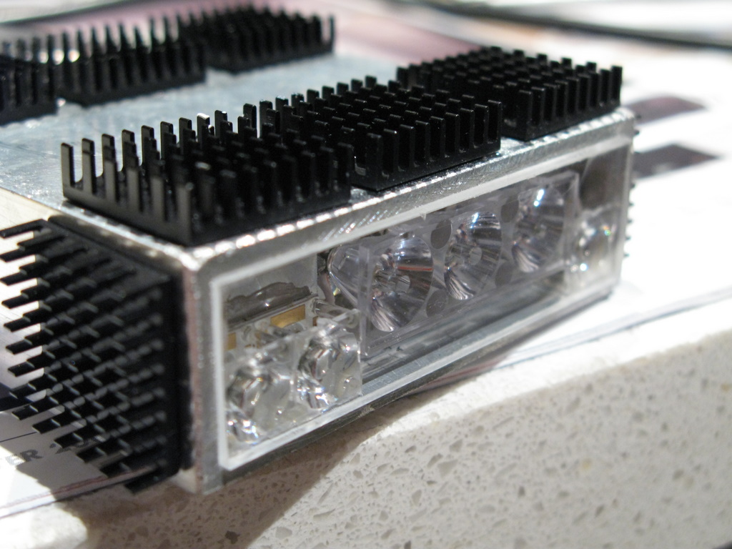
If you wanted better heat rejection from the sinks then you should have tuned them 90 deg.
Installed the way you have causes the air to past to quickly through them. Turning them 90 deg causes the air the travel slower through the heat sinks and thus absorbs more heat off them.
Just a though!
Pikey
-------------------------------------------
The bush engineer is Evil and must be employed
-------------------------------------------
the thing is.. you are assuming that the air passing over quickly will be warm from the heatsink, however what Pikey is saying is that the air is passing so quickly that the heat hasn't had enough time to transfer from the hs to the passing air, which is essentially the main requirement (removing heat from the heatsink) of cooling the whole thing down.
In any case, we shouldn't question someone who passes gas for a living!! Hot or Cold, he is the man!
Submitted by MDOldFart on Thu, 07/05/2009 - 09:41.
Loz, if you're standing outside do you feel colder when there is a gentle breeze or a strong one?
Pikey, good logic but its flawed (and I say that without any scientific basis to back me up) If they face the other way then the air flow is disturbed and only the first row or two of fins would actually have free flowing air passing over them. The way they are gives the greatest surface area of for free flowing wind to pass
Submitted by Carlgroover on Thu, 07/05/2009 - 20:20.
The slower moving air will be warmer as it's absorbed some heat and once it's done that it has less cooling effect.
Pikey you are wrong. I'm with the oldfart, and the wind chill factor.
John.
Please let the person with a trade in refrigeration and air conditioning please step forward!!!!
Read it and weep. I am not wrong!
Dynamics of Heat Transfer
Chilled-water cooling coils are finned-tube heat exchangers consisting of rows of tubes (usually copper) that pass through sheets of formed fins (usually aluminum). As air passes through the coil and contacts the cold fin surfaces, heat transfers from the air to the water flowing through the tubes.
Physically, cooling coils mark the intersection between the air distribution system and the chilled water system. Functionally, coils serve as “bridges” that permit the exchange of airside loads for chilled water loads. Improving the design of the “bridge” allows it to handle more “traffic” — that is, to transfer more heat. Better heat transfer creates opportunities to refine air and chilled water distribution in ways that best balance capital investment and life-cycle costs.
The following equation quantifies the heat-transfer process:
Q = U × A × LMTD
where,
Q = amount of heat transferred, Btu/hr (W)
U = heat-transfer coefficient, Btu/hr • ft² • °F (W/m² • °K)
A = effective surface area for heat transfer, ft² (m²)
LMTD = log-mean temperature difference across the coil surface, °F (°C)
Increasing any one of these variables (heat-transfer coefficient, surface area, or log-mean temperature difference) results in more heat transfer and ultimately improves the life-cycle value of the cooling coil.
You may think that the realm of heat-transfer technology belongs exclusively to research engineers in white lab coats. In fact, the engineer who designs the HVAC system significantly influences heat-transfer performance simply by determining the coil selection criteria.
To understand how various design decisions affect coil efficiency, let’s examine each variable individually.
Back to Table of Contents
Log-mean temperature difference, Q = U × A × LMTD
Arguably the most effective way to improve heat-transfer performance is to increase the log-mean temperature difference (LMTD). In the context of a chilled-water cooling coil, LMTD describes the difference between the temperatures of the air passing across the coil fins and the water flowing through the coil tubes:
LMTD = (TD2 – TD1) / ln (TD2 / TD1)
where,
TD1 = leaving-air and entering-water temperature difference at the coil,
°F (°C)
TD2 = entering-air and leaving-water temperature difference at the coil,
°F (°C)
One way to increase LMTD is to supply the coil with colder water. (See “Low-Flow” Coil Performance.) [1, 2]
Back to Table of Contents
Heat-transfer coefficient, Q = U × A × LMTD
Also called U-factor or thermal transmittance, the heat-transfer coefficient describes the overall rate of heat flow through the coil. Three factors determine this rate:
Airside film coefficient describes the “barrier” (resistance to heat transfer) between the passing air stream and the fin surfaces
Waterside film coefficient describes a similar “barrier” between the inside surfaces of the copper tubes and the circulating fluid
Thermal conductance describes the rate at which heat flows through the aluminum fins and copper tubes of the coil
System designers can do little to affect thermal conductance, but they wield considerable control over the film coefficients. How? By specifying velocities for the air and fluid that pass through the cooling coil. Increasing the rate of airflow reduces heat-transfer resistance on the air side of the cooling coil. Likewise, increasing the water velocity reduces the waterside resistance to heat transfer.
Fin geometry can improve the overall heat-transfer coefficient, too, by lessening the airside film coefficient. Like velocity, fin geometry can be specified as part of the design of the HVAC system. For comfort-cooling applications, coil fins are usually stamped into waveforms resembling corrugated cardboard. These waveforms create turbulence in the passing air stream, which lessens the resistance to heat transfer. More exaggerated waveforms produce more turbulence.
Turbulent water flow, like turbulent airflow, also reduces resistance to heat transfer. And, like fin geometry, it can become an important criterion for coil selection. Waterside turbulence can be created by metal ribbons or helical wires inside the tubes. Called turbulators, these devices create eddies as the water flows across them.
Both methods of improving the heat-transfer coefficient (increased velocity and turbulence) create higher pressure drops, which can mean additional fan or pump power.
Back to Table of Contents
Coil surface area, Q = U × A × LMTD
The third determinant of heat transfer is the coil’s surface area. Typically, fin spacing for comfort heating or cooling ranges from 80 to 168 fins per foot. Spacing the fins closer together multiplies the surface area by permitting more fins per linear unit. Although the airside pressure drop may increase, adding fins extends the available surface area without affecting the overall size of the coil.
Adding rows of tubes also increases the heat-transfer surface area. Most coils are constructed with same-end connections, so rows are usually added in pairs. The weight and cost of the coil increase accordingly, but the airside pressure drop may not. (Wider fin spacing often accompanies the decision to add rows.)
The best way to extend the surface area for heat transfer is to decrease the face velocity of the coil, that is, face area relative to airflow:
face velocity = airflow / face area
Face velocity can be reduced in one of two ways: by increasing the size of the coil or (paradoxically) by reducing the required airflow. Selecting a physically larger coil increases the initial investment in the coil and the air handler, and may also enlarge the air-handler footprint ... seldom desirable outcomes. So, how can we reduce the required airflow without sacrificing coil capacity?
Back to Table of Contents
Improving Coil Performance
Lowering the supply air temperature reduces the amount of air required for sensible cooling and saves fan energy.[3] From our review of the heat-transfer equation, we know that: less airflow increases airside film resistance, which reduces heat-transfer coefficient U; and requires colder air, which decreases LMTD (see effect of supply air temperature on LMTD).
To compensate for the negative effects on coil performance that accompany less airflow, we must find a way to increase U (heat-transfer coefficient) and/or A (surface area). In other words, we must select a cooling coil with better-than-average heat-transfer characteristics.
Back to Table of Contents
Increase U
Recall that turbulent flow reduces the film resistance to heat transfer. Choosing a fin configuration with a more pronounced waveform and/or adding turbulators inside the coil tubes will improve the heat-transfer coefficient.
Increase A
Any additional increase in heat-transfer capacity must be achieved by physically increasing the available surface area; that is, by:
Adding rows
Adding fins
Increasing the physical size of the coil (which will increase the initial costs of the coil, air handler, and airside accessories)
Back to Table of Contents
For example ...
The HVAC design for a 400,000 ft², seven-story office building includes blow-through air handlers (one per floor) with chilled water coils and variable-volume air distribution. Originally, the design conditions required each air handler to deliver 55,385 ft³/min of 55°F air. (See summary of results from a study that evaluated the benefit of supplying colder, 52°F air.) Neither the air handlers nor the waterside design conditions were altered.
Reducing the coil face velocity from 552 ft/min to 469 ft/min and increasing the number of fins per foot from 124 to 152 provided the additional heat transfer needed to reach 52°F. Not only was the airside pressure drop less, but the lower face velocity also alleviated concerns about moisture carryover.
In this case, improving heat-transfer performance and selecting the coils based on a closer approach (TD1) reduced the required airflow by 15 percent ... and yielded annual fan-energy savings of almost $12,000 USD.
Note: Improving coil efficiency by reducing airflow offers two benefits — it requires less fan horsepower and it reduces the cooling load (via less fan heat). Of course, cooler air may require more reheat. A detailed energy analysis should be performed to assess the economic impact on the entire HVAC system and, ultimately, on building life-cycle costs.
Back to Table of Contents
Closing Thoughts
Q = U × A × LMTD reminds us of the extent to which we preordain the capital and life-cycle costs of an HVAC system. Specifying the entering water and leaving air temperatures that all cooling coils must meet not only determines the required mass of air and water, but also the costs of moving them.
The next time that you select a coil, invest a few extra minutes to explore the LMTD effect with lower chilled water temperatures and colder supply air. You’ll find that the potential benefits are simply too attractive to ignore.
Endnotes
[1] M. Schwedler, PE, 1996, “How Low-Flow Systems Can Help You Give Your Customers What They Want,” Engineers Newsletter 26 no. 2 (La Crosse, WI: Trane).
[2] Trane, 1999, “The Low Dollar Chiller Plant,” Engineers Newsletter Live videotape APP-APV001-EN (La Crosse, WI: Trane).
[3] D. Eppelheimer, 2000, “Cold Air Makes Good $ense,” Engineers Newsletter 29 no. 2.
By Don Eppelheimer, applications engineer, and Brenda Bradley, information designer, Trane.
You can find this and other issues of the Engineers Newsletter in the commercial section of www.trane.com. To comment, send a note to Trane, Engineers Newsletter Editor, 3600 Pammel Creek Road, La Crosse, WI 54601-7599, or e-mail us at [email protected].
So there
-------------------------------------------
The untrained opinion is Evil and must be exposed
-------------------------------------------
The thermal dynamics of heat sinks in enclosed spaces is different to those in open air.
Given the number of hedgehogs used and the fact they are in open air, the direction of the fins is not going to make one iota of difference. In fact Rob could stop and lay down for a nap with his lights on and as long as he was in the open the heat would dissipate sufficiently


If you wanted better heat rejection from the sinks then you should have tuned them 90 deg.
Installed the way you have causes the air to past to quickly through them. Turning them 90 deg causes the air the travel slower through the heat sinks and thus absorbs more heat off them.
Just a though!
Pikey
-------------------------------------------
The bush engineer is Evil and must be employed
-------------------------------------------
but a damn good one!
great observation pikey!
But what about the more air passing the cooler they are
the thing is.. you are assuming that the air passing over quickly will be warm from the heatsink, however what Pikey is saying is that the air is passing so quickly that the heat hasn't had enough time to transfer from the hs to the passing air, which is essentially the main requirement (removing heat from the heatsink) of cooling the whole thing down.
In any case, we shouldn't question someone who passes gas for a living!! Hot or Cold, he is the man!
But the drag would be so great that Rob would blow up and would have to have a little sleep
Loz, if you're standing outside do you feel colder when there is a gentle breeze or a strong one?
Pikey, good logic but its flawed (and I say that without any scientific basis to back me up) If they face the other way then the air flow is disturbed and only the first row or two of fins would actually have free flowing air passing over them. The way they are gives the greatest surface area of for free flowing wind to pass
Yes - I did actually put them like that to minimise drag. Yes I did!
The slower moving air will be warmer as it's absorbed some heat and once it's done that it has less cooling effect.
Pikey you are wrong. I'm with the oldfart, and the wind chill factor.
John.
Please let the person with a trade in refrigeration and air conditioning please step forward!!!!
Read it and weep. I am not wrong!
Dynamics of Heat Transfer
Chilled-water cooling coils are finned-tube heat exchangers consisting of rows of tubes (usually copper) that pass through sheets of formed fins (usually aluminum). As air passes through the coil and contacts the cold fin surfaces, heat transfers from the air to the water flowing through the tubes.
Physically, cooling coils mark the intersection between the air distribution system and the chilled water system. Functionally, coils serve as “bridges” that permit the exchange of airside loads for chilled water loads. Improving the design of the “bridge” allows it to handle more “traffic” — that is, to transfer more heat. Better heat transfer creates opportunities to refine air and chilled water distribution in ways that best balance capital investment and life-cycle costs.
The following equation quantifies the heat-transfer process:
Q = U × A × LMTD
where,
Q = amount of heat transferred, Btu/hr (W)
U = heat-transfer coefficient, Btu/hr • ft² • °F (W/m² • °K)
A = effective surface area for heat transfer, ft² (m²)
LMTD = log-mean temperature difference across the coil surface, °F (°C)
Increasing any one of these variables (heat-transfer coefficient, surface area, or log-mean temperature difference) results in more heat transfer and ultimately improves the life-cycle value of the cooling coil.
You may think that the realm of heat-transfer technology belongs exclusively to research engineers in white lab coats. In fact, the engineer who designs the HVAC system significantly influences heat-transfer performance simply by determining the coil selection criteria.
To understand how various design decisions affect coil efficiency, let’s examine each variable individually.
Back to Table of Contents
Log-mean temperature difference, Q = U × A × LMTD
Arguably the most effective way to improve heat-transfer performance is to increase the log-mean temperature difference (LMTD). In the context of a chilled-water cooling coil, LMTD describes the difference between the temperatures of the air passing across the coil fins and the water flowing through the coil tubes:
LMTD = (TD2 – TD1) / ln (TD2 / TD1)
where,
TD1 = leaving-air and entering-water temperature difference at the coil,
°F (°C)
TD2 = entering-air and leaving-water temperature difference at the coil,
°F (°C)
One way to increase LMTD is to supply the coil with colder water. (See “Low-Flow” Coil Performance.) [1, 2]
Back to Table of Contents
Heat-transfer coefficient, Q = U × A × LMTD
Also called U-factor or thermal transmittance, the heat-transfer coefficient describes the overall rate of heat flow through the coil. Three factors determine this rate:
Airside film coefficient describes the “barrier” (resistance to heat transfer) between the passing air stream and the fin surfaces
Waterside film coefficient describes a similar “barrier” between the inside surfaces of the copper tubes and the circulating fluid
Thermal conductance describes the rate at which heat flows through the aluminum fins and copper tubes of the coil
System designers can do little to affect thermal conductance, but they wield considerable control over the film coefficients. How? By specifying velocities for the air and fluid that pass through the cooling coil. Increasing the rate of airflow reduces heat-transfer resistance on the air side of the cooling coil. Likewise, increasing the water velocity reduces the waterside resistance to heat transfer.
Fin geometry can improve the overall heat-transfer coefficient, too, by lessening the airside film coefficient. Like velocity, fin geometry can be specified as part of the design of the HVAC system. For comfort-cooling applications, coil fins are usually stamped into waveforms resembling corrugated cardboard. These waveforms create turbulence in the passing air stream, which lessens the resistance to heat transfer. More exaggerated waveforms produce more turbulence.
Turbulent water flow, like turbulent airflow, also reduces resistance to heat transfer. And, like fin geometry, it can become an important criterion for coil selection. Waterside turbulence can be created by metal ribbons or helical wires inside the tubes. Called turbulators, these devices create eddies as the water flows across them.
Both methods of improving the heat-transfer coefficient (increased velocity and turbulence) create higher pressure drops, which can mean additional fan or pump power.
Back to Table of Contents
Coil surface area, Q = U × A × LMTD
The third determinant of heat transfer is the coil’s surface area. Typically, fin spacing for comfort heating or cooling ranges from 80 to 168 fins per foot. Spacing the fins closer together multiplies the surface area by permitting more fins per linear unit. Although the airside pressure drop may increase, adding fins extends the available surface area without affecting the overall size of the coil.
Adding rows of tubes also increases the heat-transfer surface area. Most coils are constructed with same-end connections, so rows are usually added in pairs. The weight and cost of the coil increase accordingly, but the airside pressure drop may not. (Wider fin spacing often accompanies the decision to add rows.)
The best way to extend the surface area for heat transfer is to decrease the face velocity of the coil, that is, face area relative to airflow:
face velocity = airflow / face area
Face velocity can be reduced in one of two ways: by increasing the size of the coil or (paradoxically) by reducing the required airflow. Selecting a physically larger coil increases the initial investment in the coil and the air handler, and may also enlarge the air-handler footprint ... seldom desirable outcomes. So, how can we reduce the required airflow without sacrificing coil capacity?
Back to Table of Contents
Improving Coil Performance
Lowering the supply air temperature reduces the amount of air required for sensible cooling and saves fan energy.[3] From our review of the heat-transfer equation, we know that: less airflow increases airside film resistance, which reduces heat-transfer coefficient U; and requires colder air, which decreases LMTD (see effect of supply air temperature on LMTD).
To compensate for the negative effects on coil performance that accompany less airflow, we must find a way to increase U (heat-transfer coefficient) and/or A (surface area). In other words, we must select a cooling coil with better-than-average heat-transfer characteristics.
Back to Table of Contents
Increase U
Recall that turbulent flow reduces the film resistance to heat transfer. Choosing a fin configuration with a more pronounced waveform and/or adding turbulators inside the coil tubes will improve the heat-transfer coefficient.
Increase A
Any additional increase in heat-transfer capacity must be achieved by physically increasing the available surface area; that is, by:
Adding rows
Adding fins
Increasing the physical size of the coil (which will increase the initial costs of the coil, air handler, and airside accessories)
Back to Table of Contents
For example ...
The HVAC design for a 400,000 ft², seven-story office building includes blow-through air handlers (one per floor) with chilled water coils and variable-volume air distribution. Originally, the design conditions required each air handler to deliver 55,385 ft³/min of 55°F air. (See summary of results from a study that evaluated the benefit of supplying colder, 52°F air.) Neither the air handlers nor the waterside design conditions were altered.
Reducing the coil face velocity from 552 ft/min to 469 ft/min and increasing the number of fins per foot from 124 to 152 provided the additional heat transfer needed to reach 52°F. Not only was the airside pressure drop less, but the lower face velocity also alleviated concerns about moisture carryover.
In this case, improving heat-transfer performance and selecting the coils based on a closer approach (TD1) reduced the required airflow by 15 percent ... and yielded annual fan-energy savings of almost $12,000 USD.
Note: Improving coil efficiency by reducing airflow offers two benefits — it requires less fan horsepower and it reduces the cooling load (via less fan heat). Of course, cooler air may require more reheat. A detailed energy analysis should be performed to assess the economic impact on the entire HVAC system and, ultimately, on building life-cycle costs.
Back to Table of Contents
Closing Thoughts
Q = U × A × LMTD reminds us of the extent to which we preordain the capital and life-cycle costs of an HVAC system. Specifying the entering water and leaving air temperatures that all cooling coils must meet not only determines the required mass of air and water, but also the costs of moving them.
The next time that you select a coil, invest a few extra minutes to explore the LMTD effect with lower chilled water temperatures and colder supply air. You’ll find that the potential benefits are simply too attractive to ignore.
Endnotes
[1] M. Schwedler, PE, 1996, “How Low-Flow Systems Can Help You Give Your Customers What They Want,” Engineers Newsletter 26 no. 2 (La Crosse, WI: Trane).
[2] Trane, 1999, “The Low Dollar Chiller Plant,” Engineers Newsletter Live videotape APP-APV001-EN (La Crosse, WI: Trane).
[3] D. Eppelheimer, 2000, “Cold Air Makes Good $ense,” Engineers Newsletter 29 no. 2.
By Don Eppelheimer, applications engineer, and Brenda Bradley, information designer, Trane.
You can find this and other issues of the Engineers Newsletter in the commercial section of www.trane.com. To comment, send a note to Trane, Engineers Newsletter Editor, 3600 Pammel Creek Road, La Crosse, WI 54601-7599, or e-mail us at [email protected].
So there
-------------------------------------------
The untrained opinion is Evil and must be exposed
-------------------------------------------
Next thing you are going to tell us hammer pants are the next big thing in fashion!


Pikey, if you leave your radiator mounted vertically in your 4wd your admitting I'm right.
You all are talking crap.
The thermal dynamics of heat sinks in enclosed spaces is different to those in open air.
Given the number of hedgehogs used and the fact they are in open air, the direction of the fins is not going to make one iota of difference. In fact Rob could stop and lay down for a nap with his lights on and as long as he was in the open the heat would dissipate sufficiently
Go Big or Go Home
It has everything to do with the speed the air travels through the heat sink.
If the air travels to fast through the heat sink its performance is less as the air cannot absorb the heat from the sink
No further discussions shall be entered into.
Pikey
-------------------------------------------
The uneducated are Evil and must be putdown
-------------------------------------------
Sherlock Holmes
Rob neither travels fast nor rides with his head in a water filled cooling tower.