You are hereHow to Mount a Garmin Cadence Sensor on a Cannondale Rush
How to Mount a Garmin Cadence Sensor on a Cannondale Rush
This is a very quick description of how I managed to get the cadence sensor from a Garmin Edge mounted on a Cannondale Rush.
The problem with the Rush is that the rear wheel 'hangs' from a swing arm that is higher than most. Definitely higher than the designers of the Garmin sensor intended.
There were two possible options to solve this problem:
- Disassemble the sensor, mount the main body somewhere else, then extend the wiring between it and the wheel sensor and mount that on the rear arm.
- Create some kind of mount that hangs under the rear arm and holds the sensor in the location it was intended.
Although several articles can be found that describe success with the first option, the latter sounded a little easier and less prone to bad mistakes - if you don't get the measurements quiet right you've just ruined 20c worth of aluminium, not a costly sensor.
Making a mount isn't really hard at all, and took me an hour or so. The hardest part was working out where to make cuts in the aluminium angle. Luckily geometry is your friend and the numbers required are shown in the first step here:
Take a piece of angle Aluminium (this was 20x20x1.5 section). 180mm long, and make cuts leaving the following lengths:
29mm, 31mm, 54mm, 36mm, 30mm
Make a 90 degree bend at the first cut.
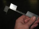
We have to remove the backing from what will become the base of the mount as shown here. This is a bit tricky, so to be honest, it's probably best to remove all the back part of the 'L' shaped section from the first bend through to the third cut.
Ie. the topmost piece in this shot could also be removed. This would not only make for a simpler cut with the hacksaw, but will leave more scope for moving the cadence sensor in/out from the wheel when it's mounted. Leaving that section there (as shown) means the sensor will stick out slightly and the mount has to be slightly rotated toward the wheel to avoid fouling the cranks.
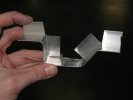
Bend the mount a few more times to complete.
Note that it's not possible to fit the sensor here because:
1. There's no way to get a cable tie round the left end of the base (where my thumb is).
2. The arm for the wheel magnet is blocked by the back of the 'L' on the right.
A few finishing touches:
1. Make a vertical cut to the back of the 'L', right of the base - this means the arm for the wheel magnet can actually be used. Handy Eye-wink
2. The back of the 'L', left has had a section removed from the bottom. This allows room for the cable tie required to hold the sensor in place. Although as I said earlier, it's probably best to remove this whole piece to be honest.
3. At the extreme left/right make two cuts and small fold in the horizontal part of the mount. These should be measured against the frame - they 'grip' the brake cable routing mounts which stops the whole thing shifting up and down the swingarm.
4. Round off all the sharp corners and stuff of course.
The final mount positioned on the left, rear swing arm.
The rear cable tie (had to use two connected to get the length) goes through the 'V' shape made top of the arm forward.
Finished product with sensor attached.
There's really not much space between the crank and sensor. As mentioned a couple times, removing the back of the 'L' completely, where the sensor mounts would allow it to be closer to the wheel and give more room here.
Note how the small 'fold' at the end of the mount is pulled tight up against the brake host mount - same deal at the front prevents movement.
Job done - how easy was that? 
- Login to post comments


So this is good stuff. I had just decided that I could cope with only the speed since a long and difficult evening dicking around with the sensor brought me to the conclusion that I would not be too worried about cadence (grapes were sour anyway, right?) and mounted it with cable ties right down at the brake assembly to at least get speed.
Modifications will be made, specially now its such a crappy weekend.
Hey Rob, have you ever mounted the sensor to your Yeti? I just attached one to mine but I'm not 100% happy with it.
Nah... the Yeti is my 'fun' bike... no sensors required
Can't think why it's tricky, isn't the rear arm too high?
The problem stems from where the brake line attaches to the top of the chainstay. It's right at the optimum distance of where you put the magnet on the crank arm. The brake hosing gets in the way a bit. I've had to feed my brake line higher up onto the seatstay and then cable tie it all the way down to the caliper. Also the speed sensor arm feels quite exposed. Looks like it would snap off you you got something jammed in between the wheel and the frame.
I was looking at mine on the w/e for the same, and there is a hose run right in the only place you can mount the sensor and get both cadence and speed. Might have to mold a few carbon fibre brackets to fit these to a range of FS bikes?
Would they sell do you think?
Rob, I know what you mean about fun bikes. OzMot gave me heaps when I said I was looking to mount it to the 575 . I'll have to get a scumooter instead.
I'll take a photo of my setup and post it up.
You doing the Fling?
Looking forward to
a hot shower on Sunday nightten hours or less of pedalling, and a cold beer.//Devils advocate mode: ON//
What on earth are you worrying about cadence on your MTB for? How often can you maintain a steady cadence off road anyway? Also cadence is only useful when training, which you do most of on the road. Stick it on the crosser where it would be more use.
//Devils advocate mode: OFF//
The opinions in the post do not necessarily represent a knowledgeable man.
But I'm curious to see what cadence I can achieve and also to keep an eye on it during the Fling.
The sensor is for cadence and distance. It's suppose to use both the sensor and GPS to get more accurate distance measurements than GPS alone would do.
That said, I'm not convinced it has an effect. So yes - this sensor may well end up on the crosser.