
You are hereRob's Homemade LEDs - Electronics
Rob's Homemade LEDs - Electronics

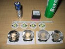
Parts purchased from Cutter Electronics... Cree XR-E LEDs, Luxdrive Buckpuck and L2 Optics... erm... optics and diffusers.
Plus an AA battery and Berocca tube for scale.
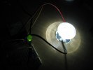
Testing Cree XR-E LEDs... on the right is a single XR-E with L2 Optic mounted. This is driven from the Luxdrive 3021 BuckPuck with about the lowest current that it can supply and still have the LED light - about 5mA! On the left is a 'standard' green LED for comparison.
This is pretty amazing given the Cree can be driven up to 700mA or with 140 times more current.
Best laid plans
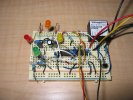
Ah yes - and it all seemed so simple... the 3021 data sheet explained how one should feed somewhere between zero and five volts to it's control pin to control the light output level from the LEDs connected. I have a Petzl LED headlight which works with a single push button to cycle through four stages of off->full->dim->dimmer->off. Simple enough to replicate I soon had a J-K flip flop design made up, driving what was basically three logic controlled voltage dividers to connect to the control pin of a 3021. Prototyped on a breadboard and with a standard LED placed where the control pin should be, sure enough this changed the brightness of the LED and therefore the voltage going in, and would therefore work the 3021. Erm... well, as it happens, no!
Once the parts arrived it was sadly discovered that no amount of tinkering or experimentation could cause the 3021 to work as anticipated with the logic controlled dimmer. Back to the drawing board.
Keep it Simple
More experimentation followed and as it turns out the dimming function of the 3021 is purely a product of the resistance between Vref and Control. I found that 280ohms gave around the dimmest level possible, while anything over 2K seemed pretty much indistinguishable from no dimming at all. Leaving the control pin with no connection meant the 3021 pumped out full brightness.
Plan 'B' developed as a simple three position switch that would toggle between no connection (full power) and two separate resistance networks for two different dimming levels. Tried out and tested - this worked perfectly.
In the mean time, someone had persuaded me that running this circuit with a high current (it would be drawing around 0.8-0.9A) from batteries with no over-discharge protection was asking for trouble, so decided to use the space now available on the circuit board for low and dead battery warning and protection. Indeed, searching around the 'net one discovers that the recommended discharge for a 1.2V NiMH cell is 1.0v - anything less is risking damage, especially when the cells can be in large packs (I was planning to have a 16 cell pack).
The idea was simple enough - use two voltage dividers and an op-amp as comparator (comparing to Vref) to get low and dead battery logic triggers. Thankfully the 3021 did behave as shown on it's data sheet with regards to logic controlled on/off switching so that would be used to turn the main LEDs off as the batteries discharged.
Oh - and why not build a simple flashing circuit also, that could 'blink' the main LEDs as a low battery warning before that cut out? Sounded like a good idea, and it was (see later on how this worked out).
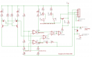
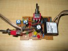
This is the second control circuit tried, and it actually works, so that's a plus 
Most of what you see here is for a nice low battery warning feature which will 'blink' the main lights about 4 times a minute when the battery is getting low. The plan was that there would be a complete cut-off a little later. Cunningly though, this complete cut-off caused a feedback effect and actually meant that the lights dim very nicely as the battery discharges.
If you're not interested in this warning the only stuff of interest should be the 270+500 trim and 470+1K trim resistance networks and switch between them. If you don't want dimming of course, forget that part.
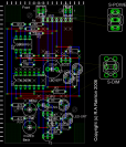
The schematic as laid out on veroboard. Blue = copper on the back, red = wires on the front, white crosses = where to cut tracks on the back.
Note that the power wires will actually be connected just South of the capacitor, but the other unconnected (yellow) wires do indicate pretty well where the dimmer switch will be connected.
Here's most of the circuit prototype on a breadboard.
What is notably absent was the test of battery low voltage comparison, although the logic to 'blink' the main LEDs when given a low warning was tested.
The voltage test was meant to be the easy part but a slight miscalculation saw a bit of work with the de-soldering braid... doh!

Before starting to solder stuff up it's best to cut the Veroboard and make sure it will fit in the enclosure and has the required number of tracks left after cutting.
There's a couple of unplanned chops top of the board here - they are to make it fit round the slots in the planned enclosure. Luckily that track didn't figure in the final design so no biggie.
Note I only bothered to drill two support holes at this stage also - the PCB was very easy to drill so didn't worry too much about doing the others when it was working.
It was all looking good here, so away we go.
Bare circuit board awaiting fitting in the enclosure.
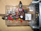
Although the PCB was used as a template somehow the holes thought the transparent box and into the aluminium frame didn't quiet mesh and those PCB holes had to be enlarged (on the right - lucky there was room).
The switches have waterproof 'boots' and all other holes will be filled with sealant to make this pretty much water tight.
Back switch (left in photo) is on/off, on being down so it won't get knocked 'off' if by some chance we hit any hanging branches. Left switch (top in photo) gives three position dimming.
Two trim pots (blue - to the left of the photo) give adjustment for the two lower 'dim' levels.
Bill of Materials
| What | Source | Cost | |
|---|---|---|---|
| Cree XR-E LEDs (U bin1 on round MCPCB) x 4 | Cutter | $56.10 | |
| Luxdrive 3021 BuckPuck (700mA, external dimming) | Cutter | $35.68 | |
| L2 Optics Lens + diffuser x 4 | Cutter | $39.38 | |
| 74LS00 IC | Jaycar | $0.60 | |
| LM358 IC | Jaycar | $1.50 | |
| NPN Transistor (BC337) x 2 | Jaycar | $0.72 | Or BC547 to save 32c |
| PNP Transistor (BC557) | Jaycar | $0.26 | |
| Various LEDs (5mm) x 4 | Jaycar | $1.00 | |
| 500ohm Piher horizontal trimpot | Jaycar | $0.75 | |
| 1Kohm Piher horizontal trimpot | Jaycar | $0.75 | |
| 10uF/16v capacitor | Jaycar | $0.20 | |
| 220uF/50v capacitor | Jaycar | $0.80 | |
| Various resistors (1K x 4, 91K x 2, 5K x 2, 270ohm, 470ohm, 24K, 27K, 130K, 150K, 160K, 2.2M) | DSE | $0.96 | Because Jaycar don't sell them individually |
| Machined pin IC socket strips (32 way) | Jaycar | $2.80 | Thought the 3021 would fit in here. It did not, so used them for transistor sockets. |
| 8 pin production IC socket | Jaycar | $0.25 | |
| 14 pin production IC socket x 2 | Jaycar | $0.56 | Chop one in half to mount the 3021 in. |
| SPDT miniature toggle switch | Jaycar | $2.20 | |
| DPDT miniature toggle switch (ON - OFF - ON) | Jaycar | $3.65 | |
| Waterproof hood for miniature toggle switch x 2 | Jaycar | $2.70 | |
| Veroboard (95x76mm) | Jaycar | $3.80 | |
| Moisture proof fuse holder | Jaycar | $1.95 | |
| Hook up wire (assorted pack) | Jaycar | $2.55 | |
| Cable for LED (light duty speaker cable) x 1m | Jaycar | $0.42 | |
| Total | $159.58 |
- Login to post comments